3.5 inch Bay Mount Firewire/USB 2.0/Audio Panel Installation Instructions
Revision 1.1 © 2004 Quietpc.com
These instructions will tell you how to install your new UF-31 Front Panel Unit in an easy-to-follow manner. If you are used to taking the lid off your PC, you should find the installation reasonably straightforward. You may like to print out these instructions so you can refer to them while you are upgrading your machine. However, if you are in any doubt as to your own competency in PC hardware installation then for the safety of yourself and your PC, please ask an expert engineer to do the work for you! These instructions are for guidance only and no responsibility or liability can be borne by QuietPC.com for damage or loss incurred, (including data loss) howsoever caused, either directly or consequentially.
IMPORTANT: Before starting, ensure you have backed-up the data on your hard drive. You should be in the habit of doing this regularly in any case, as hard drives are never 100% reliable and total data loss can be disastrous if no other copy exists. The hard drive is at a higher than normal risk of failure due to accidental damage while a PC upgrade is in progress.
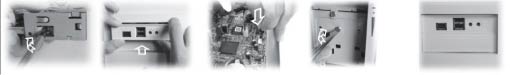
1. Getting Started
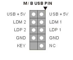
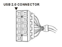
2. Pin Arrangement on the Standard USB 2.0 Cable
a) The USB 2.0 is backwards compatible to USB 1.1. Before connecting the USB 2.0 cable, please make sure that your motherboard offers a USB 2.0 interface. The easiest way to check this is to look at the detailed descriptions of the various interfaces outlined in your motherboard manual. Most frequently, there will be a picture of the pins the cable attaches to. The number of pins on your motherboard might not always equal the number of connectors on the USB cable. This does not affect the installation steps outlined in this document.
b) Each pin is strictly defined. Please review the diagrams below, which will help you install the USB cable fast, safely, and easily. Any installation mistake may cause severe damage to your motherboard and other components.
c) The USB 2.0 connector is designed to prevent installation errors. Please connect the USB 2.0 port and Motherboard (M/B) USB pin. See diagrams below.
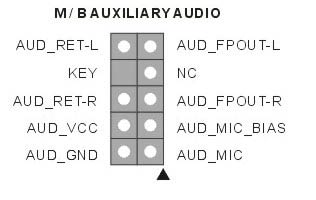
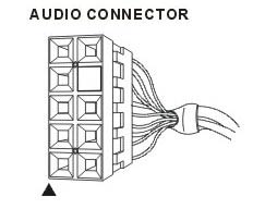
3. Pin Arrangement of the Audio Cable
a) Before connecting the audio cable, please make sure that your motherboard is compatible with Auxiliary Audio. The easiest way to check this is to look under the detailed descriptions of the various interfaces in your motherboard’s manual. Most frequently, there will be a picture of the pins you connect the cable to.
b) Each pin is strictly defined. Please review the diagrams below, which will help you install the audio cable fast, safely, and easily. Any installation mistake may cause severe damage to your motherboard any other components.
c) Remove the 5-6, 9-10 connecting jumpers from the audio pins on your M/B. Please note: the jumpers are removed ONLY when there is an audio portion on the M/B.
d) The Audio connector is designed to prevent installation errors. Please connect the audio port and M/B audio pin. See diagrams below.